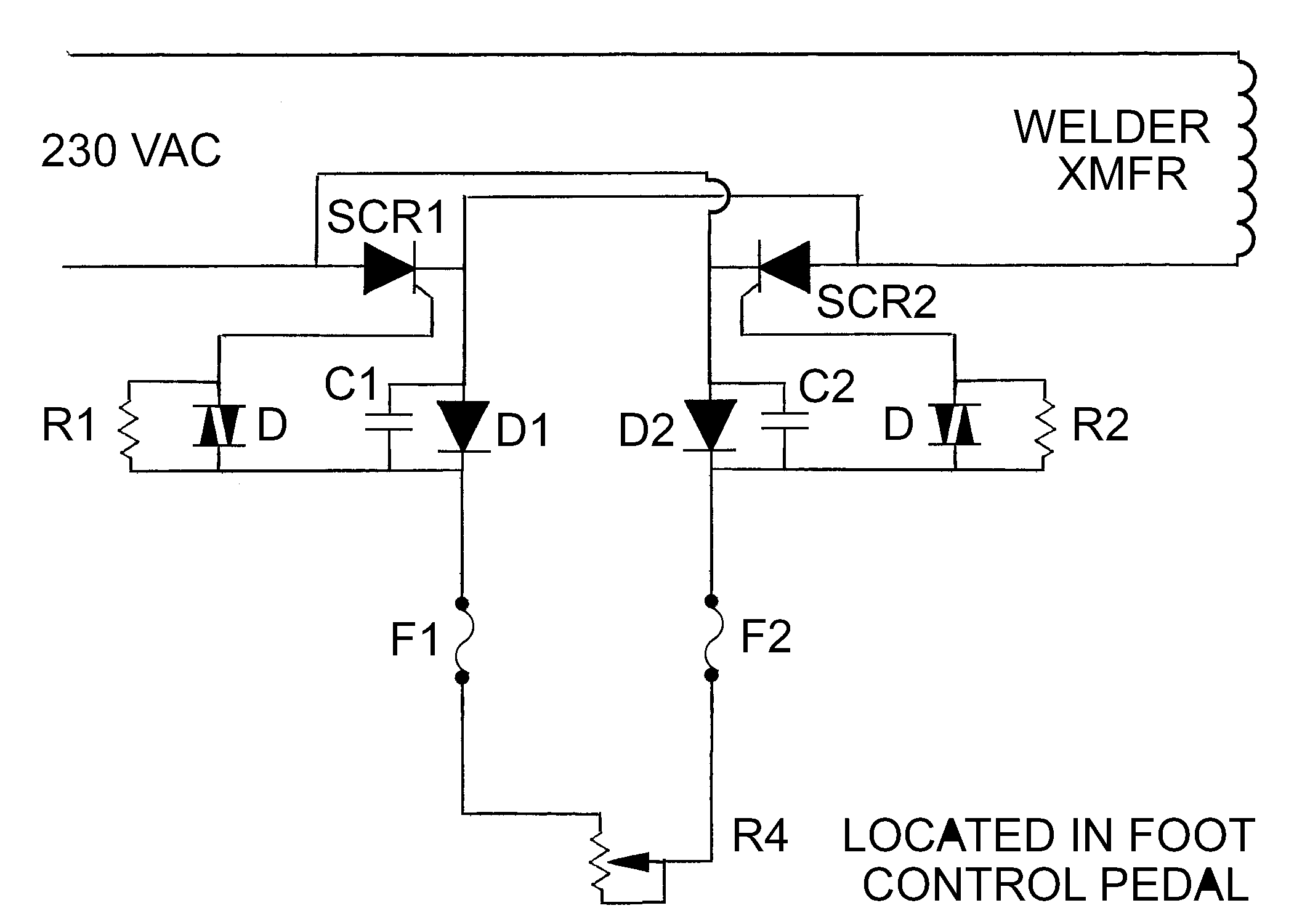


| This circuit should be installed inside the welder or in a separate box between the welder input power cable and your line voltage. It is rated for 50 amps, if a larger circuit is needed change the SCR's to a higher amperage. To print the schematic place your mouse cursor over the image and right click your mouse, then select print target. You will need to make a foot pedal to house variable resistor R4. You will also need to use your skills to have the foot pedal rotate the variable resistor. |
| The following electronic parts can be obtained from Mouser.. |
|
